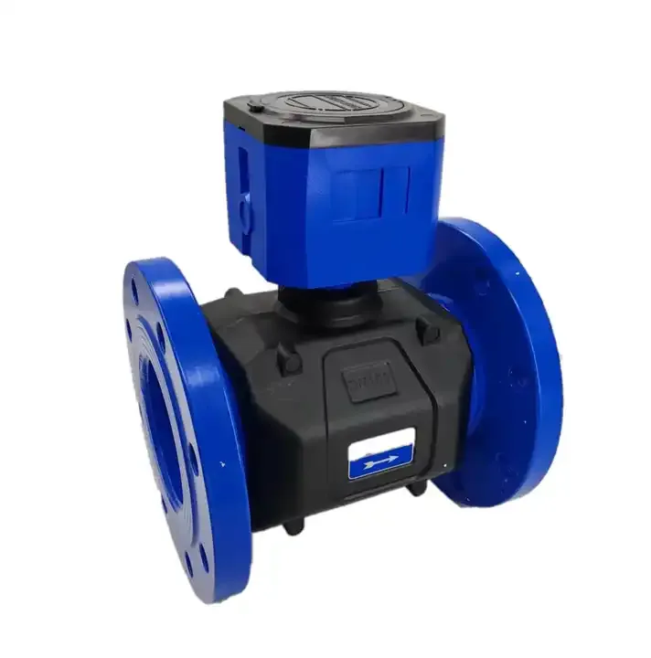
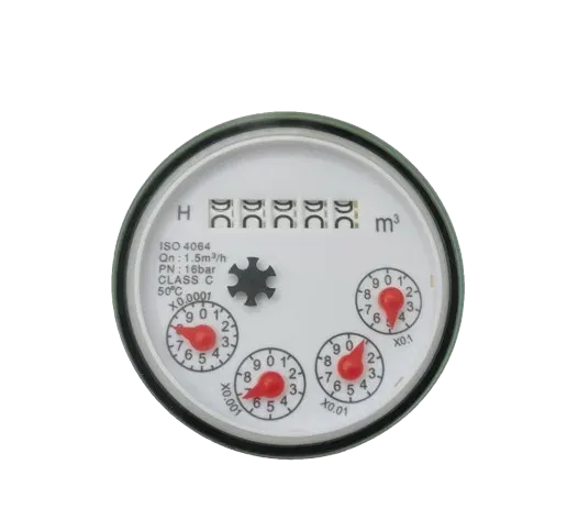
Woltman Cold Hot Water Meter
Woltman Meters in DMA: Placement and Pulse Output
Where to place a Woltman meter at a DMA boundary, how to set pulse volume and output type for night flow logging, and the error that hides leakage.
The first article in this pair covered how to size a boundary meter for a district metered area: start from the minimum night flow, read Q1 rather than Q3, and check the series rather than the family name. This one covers what happens after the size is chosen. A correctly sized meter installed in the wrong place, or read at the wrong resolution, produces the same flat night flow curve as an undersized one. The meter is no longer the problem; the installation and the data path are.
Where the meter goes at the boundary
A DMA boundary meter has to sit on the only path water takes into the area. Three constraints matter more than the rest.
Single entry. If the district has a second feed that is not metered, the boundary reading is not the district's consumption and night flow analysis loses its meaning.
Straight run upstream. A Woltman meter is sensitive to swirl. Give it the upstream straight length the manufacturer specifies. A bend or a partly closed valve directly before the meter biases the reading low at low flows, which is the exact regime you are trying to measure. Our installation and straight pipe requirements note covers the minimum lengths by size.
Access for proving. The meter must be reachable for verification and for pulse output checks without shutting the district down.
Valve position and strainer placement belong on the same drawing. A strainer downstream of the meter protects nothing that matters and adds pressure loss after the measuring element.
If your installation drawing needs checking against the meter's straight-length requirement, our installation and straight pipe requirements note lists the minimum upstream and downstream lengths by size.
Pulse output: set the resolution before the hardware
Pulse output is what turns a meter into a data point. Two decisions have to be made early.
Pulse volume. The range supports 1000 litres per pulse, 100 litres per pulse and 10 litres per pulse for DN50 to DN200, and 10000 or 1000 litres per pulse for DN250 to DN300. At a DN100 boundary, 10 litres per pulse gives usable night-time resolution. At 1000 litres per pulse a slow leak is quantised out of existence.
Pulse type. Reed switch and Hall effect pickups behave differently. A reed switch has a maximum switching frequency and can miss pulses at high flow. A Hall sensor needs a supply and is less tolerant of bounce. If the logger is an existing SCADA RTU, confirm its input type before ordering, because the meter option has to match it.
Also confirm that the register is ordered with the pulse output fitted at the factory. Adding a pulse head to a mechanical register in the field is a different part and often a different cost.
One more constraint that catches people out: the logger's scan interval and the pulse volume have to agree. A logger that polls once every fifteen minutes will miss pulses that arrive faster than that, so a very fine pulse volume is wasted on it. Match the pulse volume to the resolution the analysis actually needs, then confirm the logger can keep up.
The mistake that shows up six months later
The pattern repeats often enough to be worth naming. A district is retrofitted, the boundary meter is chosen to match the existing pipe, the DMA goes live, and the night flow curve comes back flat and slightly above zero. The team reads that as no significant leakage and moves on.
What actually happened is that the meter's Q1 sat above the district's real night flow, so the register rounded the leakage down to nothing. The district was never measured. It was only metered.
The check is simple and worth doing before selection: take a night reading by hand, or from a portable clamp-on, at the lowest flow you expect, and compare it against Q1 for the size you plan to buy. If the margin is thin, move up one accuracy class rather than up one diameter.
When a boundary meter does register but reads low under normal flow, our maintenance and field troubleshooting guide lists the usual causes in order.
If you have not read the sizing side yet, start with Woltman meters in DMA: sizing by minimum flow, which explains how Q1 is chosen against the night flow floor.
Why our installation advice holds up in the field
We are a manufacturer, not a reseller. Our production plant covers 100,000 square metres in Xingtai, Hebei, and has done since 2017. We build both the meter bodies and the mechanisms inside them in-house, from casting and machining through to assembly and calibration.
Large-diameter meters are where most sizing errors get caught late, because a DN200 boundary meter is not something a utility can swap out on a whim. We run five large-diameter test benches, so every meter in this range is flow-tested against its own calibration curve before it ships, rather than being sampled from a batch.
That is also why we can tell you when the right answer is a smaller meter than your pipe suggests. The recommendation comes from what we see on the bench, not from a catalogue page.
What to send us before you order
For a boundary installation we need the pipe diameter and material, the water type (treated, raw or effluent), the logger or SCADA model with its input type listed, and a sketch or description of the chamber layout including the nearest upstream bend or valve.
With those we can confirm the straight length is achievable in your chamber, recommend the pulse volume that matches your logger, and tell you if the layout needs changing before the meter is ordered rather than after it is installed.